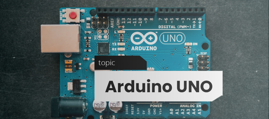
The Arduino UNO is an open- source micro-controller based on the Microchip ATmega328P micro-controller and developed by Arduino.cc. The board is equipped with sets of digital and analog input/output (I/O) pins that may be interfaced to various expansion boards (shields) and other circuits.
The board has 14 Digital pins, 6 Analog pins, and programmable with the Arduino IDE (Integrated Development Environment) via a type B USB cable. It can be powered by a USB cable or by an external 9 volt battery, though it accepts voltages between 7 and 20 volts. It is also similar to the Arduino Nano and Leonardo.
The hardware reference design is distributed under a Creative Commons Attribution Share-Alike 2.5 license and is available on the Arduino website. Layout and production files for some versions of the hardware are also available. “Uno” means one in Italian and was chosen to mark the release of Arduino Software (IDE) 1.0. The Uno board and version 1.0 of Arduino Software (IDE) were the reference versions of Arduino, now evolved to newer releases. The Uno board is the first in a series of USB Arduino boards, and the reference model for the Arduino platform. The ATmega328 on the Arduino Uno comes pre-programmed with a bootloader that allows uploading new code to it without the use of an external hardware programmer.
 It communicates using the original STK500 protocol.The Uno also differs from all preceding boards in that it does not use the FTDI USB-to-serial driver chip. Instead, it uses the Atmega16U2 (Atmega8U2 up to version R2) programmed as a USB-to-serial converter.
General Pin functions:
- LED: There is a built-in LED driven by digital pin 13. When the pin is HIGH value, the LED is on, when the pin is LOW, it’s off.
- VIN: The input voltage to the Arduino/Genuino board when it’s using an external power source (as opposed to 5 volts from the USB connection or other regulated power source). You can supply voltage through this pin, or, if supplying voltage via the power jack, access it through this pin.
- 5V: This pin outputs a regulated 5V from the regulator on the board. The board can be supplied with power either from the DC power jack (7 – 20V), the USB connector (5V), or the VIN pin of the board (7-20V). Supplying voltage via the 5V or 3.3V pins bypasses the regulator, and can damage the board.
- 3V3: A 3.3 volt supply generated by the on-board regulator. Maximum current draw is 50 mA.
- GND: Ground pins.
- IOREF: This pin on the Arduino/Genuino board provides the voltage reference with which the microcontroller operates. A properly configured shield can read the IOREF pin voltage and select the appropriate power source or enable voltage translators on the outputs to work with the 5V or 3.3V.
- Reset: Typically used to add a reset button to shields which block the one on the board.
Each of the 14 digital pins and 6 Analog pins on the Uno can be used as an input or output, using pinMode(),digitalWrite(), and digitalRead() functions. They operate at 5 volts. Each pin can provide or receive 20 mA as recommended operating condition and has an internal pull-up resistor (disconnected by default) of 20-50k ohm. A maximum of 40mA is the value that must not be exceeded on any I/O pin to avoid permanent damage to the micro-controller.The Uno has 6 analog inputs, labeled A0 through A5, each of which provide 10 bits of resolution (i.e. 1024 different values). By default they measure from ground to 5 volts, though is it possible to change the upper end of their range using the AREF pin and the analog Reference() function.
The above is a brief about Arduino Uno. Watch this space for more updates on the latest trends in Technology.